
Fuel cells are energy systems that generate electricity through electrochemical reactions. Compared to green energy sources and other conventional energy production systems, they stand out with their high efficiency despite their high investment costs. They can be classified into six main categories based on electrolyte type, operating temperatures, and fuel type: Proton Exchange Membrane Fuel Cell (PEMFC/PEFC), Alkaline Fuel Cell (AFC), Phosphoric Acid Fuel Cell (PAFC), Molten Carbonate Fuel Cell (MCFC), Solid Oxide Fuel Cell (SOFC), and Direct Methanol Fuel Cell (DMFC). PEM fuel cells are distinguished by their high efficiency, fast start-stop, low operating temperatures, and their suitability for portable applications.
Components of PEM a Fuel Cell
It essentially consists of an anode, cathode (electrode), membrane (electrolyte), bipolar plate, and gaskets. The membrane is a polymeric layer that separates the electrodes. It allows the conduction of hydrogen ions while preventing the passage of electrons and gases. The electrodes consist of a gas diffusion layer and a catalyst layer. The gas diffusion layer has a porous structure and ensures the homogeneous transport of gases to the catalyst. Catalysts ease these electrochemical reactions. Bipolar plates are components located on both sides of the cell that transfer gases to the electrodes, provide electron transport, and manage water and heat. Gaskets ensure a tight seal in the system.
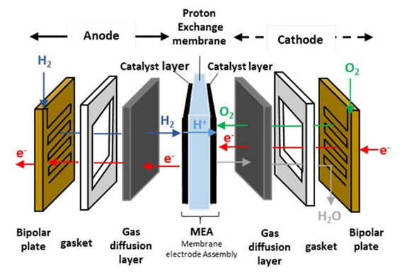
Figure 1. Components of PEM fuel cells.
Working Principle of a PEM Fuel Cell
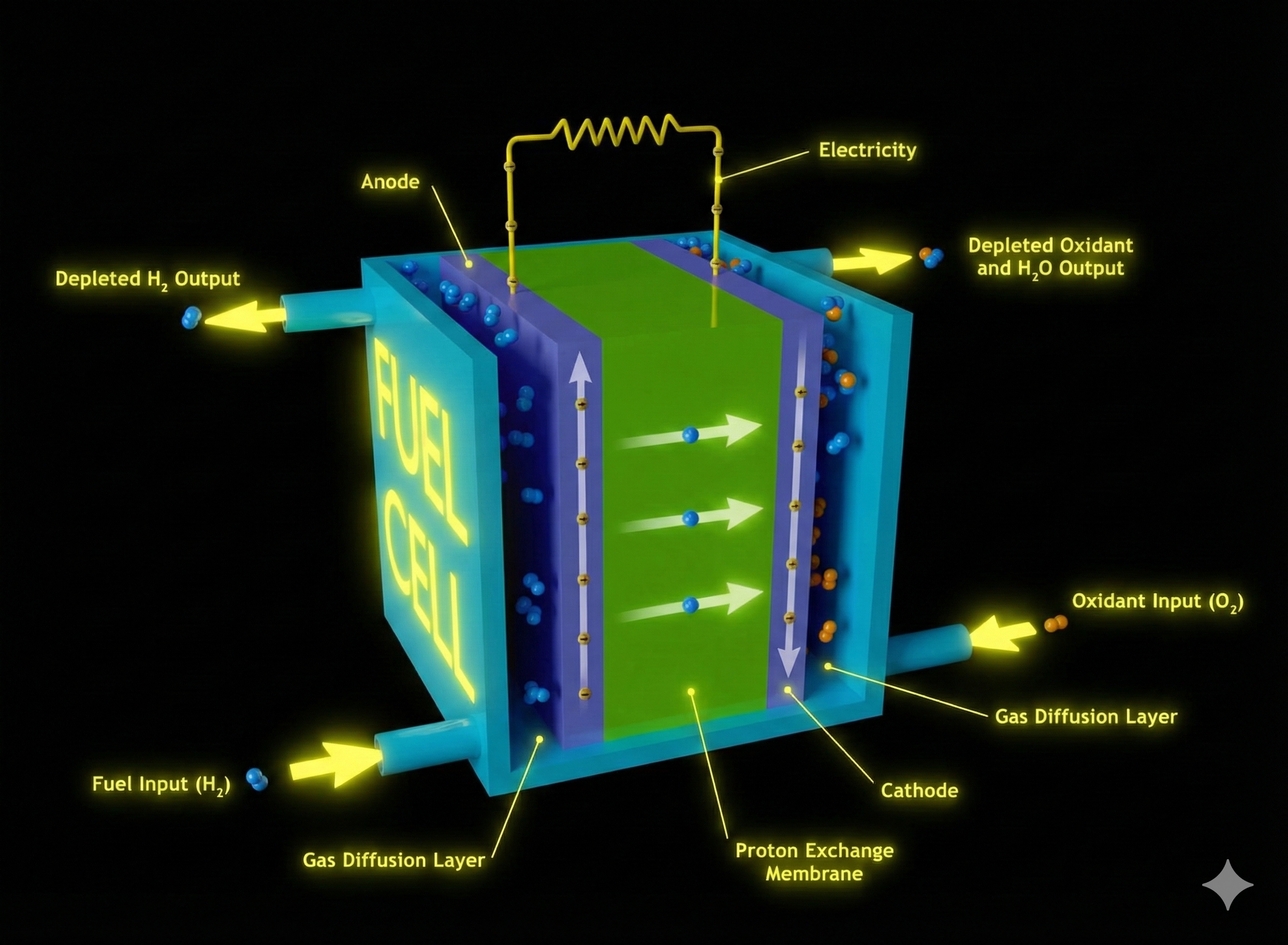
Fuel cells are devices that generate electricity through the electrochemical reactions of the gases used. So, how does this process occur? H₂ gases are fed to the anode and O₂ gases to the cathode. Hydrogen is oxidized at the anode. The hydrogen ions released as a result of this reaction travel through the membrane to the cathode. Electrons, in turn, reach the cathode through an external circuit. The oxygen fed to the cathode combines with hydrogen ions and electrons, resulting in reduction and the formation of water. With the continuous supply of gases, these reactions continue, creating a continuous flow of electrons from the anode to the cathode. This is how electricity is generated.
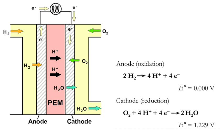
Figure 2. Schematic illustration of a PEMFC and the reactions taking place when hydrogen gas is used as a fuel.
Cyclic Voltammetry Analysis of Catalysts
Catalysts can be produced using various techniques, such as physical or chemical methods. Characterization of the produced catalysts is a crucial step in the process. Characterization of the catalyst layer also provides insight into the behavior of the MEA. One of the properties that can be examined in the produced catalysts is ECSA (Electrochemical Active Surface Area). Cyclic voltammetry, an electrochemical characterization technique, is used to determine this. The experimental setup generally consists of an electrochemical cell and a potentiostat. The potentiostat, connected to a computer, enables the experiment to be performed in the electrochemical cell.
Cell configurations can vary, but the most common and reliable system is the three-electrode cell. The three-electrode cell consists of a working electrode, a reference electrode, a counter electrode, and an electrolyte. The electrolyte provides ionic conductivity. 0.5 M H₂SO₄ and 1 M HClO₄ are commonly used electrolytes. The catalyst is used as the working electrode and is the electrode where the reactions occur. The reference electrode is the electrode that has a nonchanging potential in the solution and is used as a reference point for potential measurement. Potential is applied by taking the potential value of the reference electrode as reference. The Standardthis Calomel Electrode (SCE) and the Reversible Hydrogen Electrode (RHE) are commonly used reference electrodes. The counter electrode is used to complete the circuit. The applied potential and current are transmitted through this electrode. Platinum wire is most commonly used counter electrode.
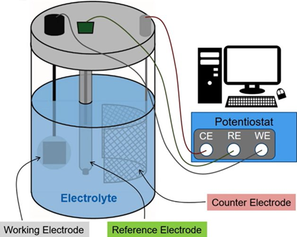
Figure 3. Schematic representation of a three theseelectrode electrochemical cell connected to a potentiostat.
In cyclic voltammetry experiments, a potential is applied cyclically to the cell within a specified potential range. In CV experiments of catalysts, the formation of H₂ or O₂ is not investigated. Therefore, the potential range used is one that does not allow these reactions to occur. Considering this, the lower limit is approximately 0.05 V, and the upper limit is 1.20 V. Thewirese values are determined form the standart electrode potential of related reactions. It is important to note that the potential applied to the cell is applied by taking the potential of the reference electrode as a reference. Potential values in the voltammogram obtained from the experiment may differ depending on the reference electrode used. The important factor is the potential range over which the scan is performed.
The graph obtained from the CV experiment is as shown below. At low potentials, hydrogen adsorption and desorption are observed, while at high potentials, Pt–O formation and reduction are observed. The hydrogen adsorption charge obtained from the graph is used in the ECSA calculation. ECSA represents the active surface area where reactions occur on the catalyst and differs from the geometric area. The main reason for this is the porous structure of the surface. The surface topography is not taken into account in the geometric area.
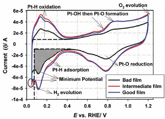
Figure 4. Comparison of CVs obtained with the bad, intermediate, and good catalyst films. CVs recorded at 20 mV s-1 in N2-saturated 0.1 M HClO4 at 30 °C. The shaded region shows the area integrated for hydrogen adsorption.
The formula for ECSA is shown below. The adsorption charge is obtained by integrating the hydrogen adsorption area. The constant 210 µC cm⁻² represents the amount of charge per unit area required to fully cover the polycrystalline platinum surface with hydrogen. Lₚₜ represents the platinum loading on the catalyst, and A₍g₎ represents the geometric surface area of the working electrode. The ECSA value is obtained as a result of the calculation.
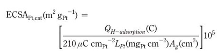
Figure 5. The formula for ECSA.
References
Garsany, Y., Baturina, O. A., Swider-Lyons, K. E., & Kocha, S. S. (2010). Experimental methods for quantifying the activity of platinum electrocatalysts for the oxygen reduction reaction. Analytical Chemistry, 82(15), 6321–6328.
Elgrishi, N., Rountree, K. J., McCarthy, B. D., Rountree, E. S., Eisenhart, T. T., & Dempsey, J. L. (2018). A practical beginner’s guide to cyclic voltammetry. Journal of Chemical Education, 95(2), 197–206.
Bard, A. J., Faulkner, L. R., & White, H. S. (2022). Electrochemical methods: Fundamentals and applications (3rd ed.). Wiley.
Hirschenhofer, J. H., Stauffer, D. B., Engleman, R. R., & Klett, M. G. (1998). Fuel cell handbook (4th ed.). Parsons Corporation. Prepared for the U.S. Department of Energy, Office of Fossil Energy, Federal Energy Technology Center
Hi, this is a comment.
To get started with moderating, editing, and deleting comments, please visit the Comments screen in the dashboard.
Commenter avatars come from Gravatar.